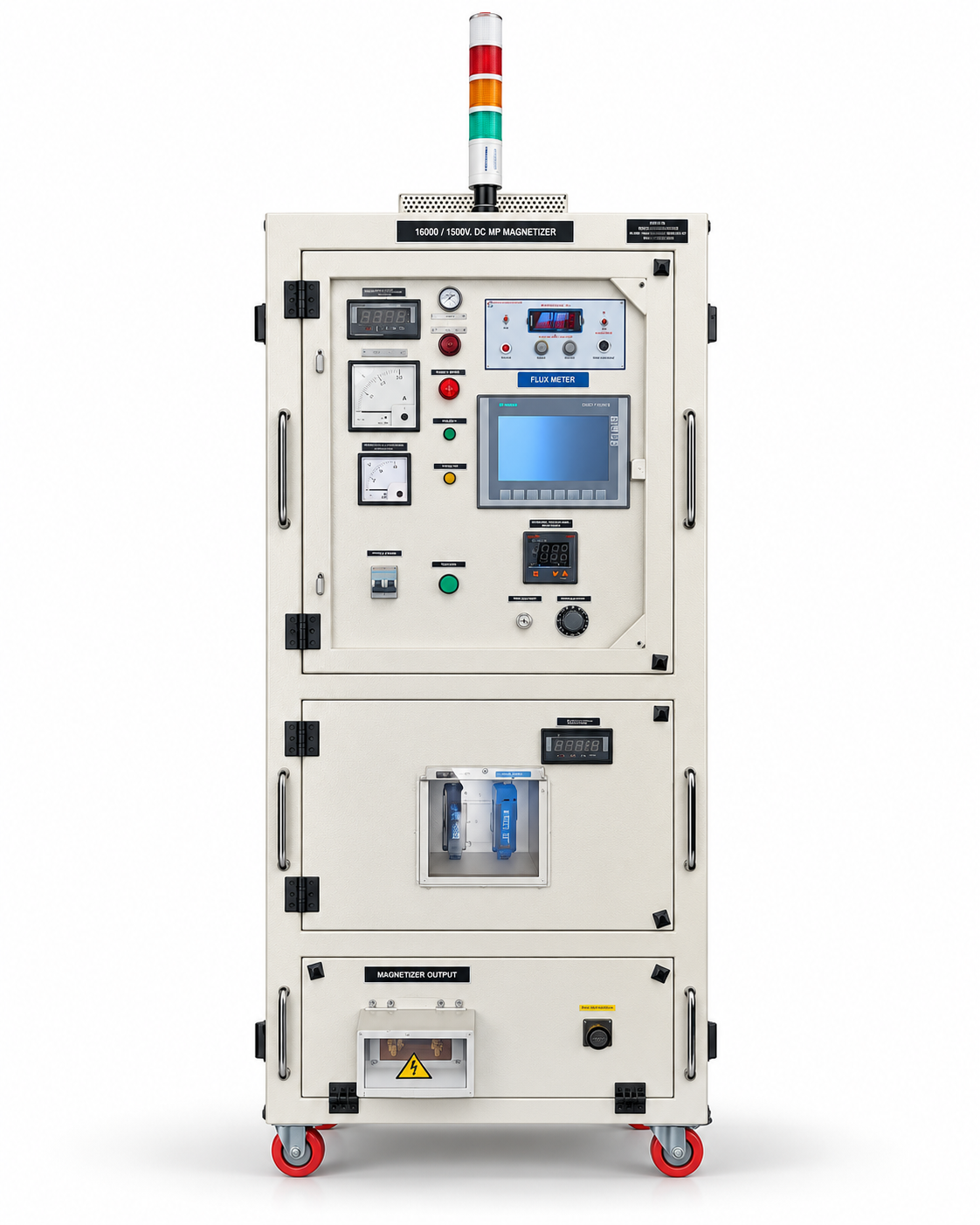
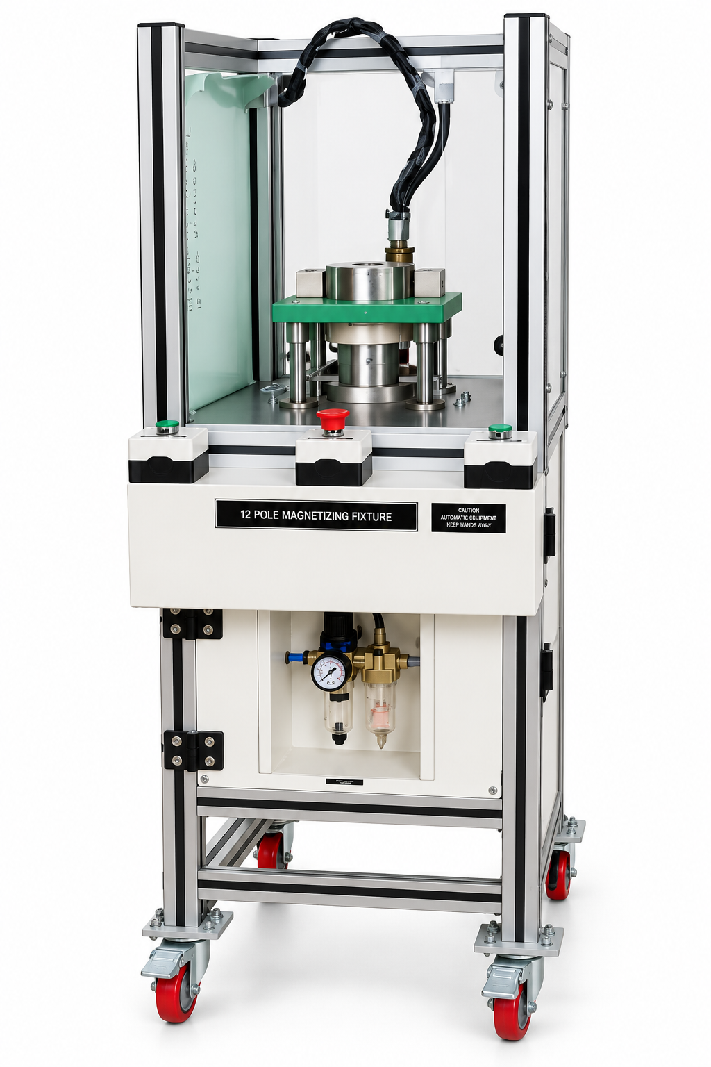
Most permanent magnets in motors, loudspeakers and sensors are magnetized by the same kind of machine: a capacitor discharge (CD) magnetizer. From the outside it looks like a control cabinet with a coil or fixture attached. Inside, it does something quite simple. It stores electrical energy slowly, then releases it all at once.
Key takeaways
- A CD magnetizer has four main building blocks: a charger, a capacitor bank, a high-current switch (usually a thyristor, also called an SCR) and a magnetizer coil or fixture.
- Stored energy follows E = ½CV², so the charging voltage has the biggest influence on how much energy each pulse carries.
- A typical pulse lasts a few milliseconds, with peak currents from a few kiloamps to tens of kiloamps.
- The coil or fixture is part of the electrical circuit. Its inductance and resistance set the height, length and shape of the pulse.
- Eddy currents in conductive parts, such as NdFeB magnets and steel housings, resist very short pulses, so pulse length matters as much as peak current.
The four building blocks
1. Charger
The charger takes power from the mains and converts it to high-voltage DC to charge the capacitors. It works over seconds rather than milliseconds, so it draws a moderate current from the supply even though the pulse it prepares is enormous. Charger power decides how quickly the bank refills between shots, and is one of the main limits on cycle time.
2. Capacitor bank
The capacitors are the energy reservoir. A bank is built from many capacitors connected in series and parallel to reach the required voltage and capacitance. The energy it stores is:
E = ½ × C × V²
where C is the capacitance in farads and V is the charging voltage in volts. Because voltage is squared, doubling the voltage on the same bank stores four times the energy.
3. Switch
When the operator presses the fire button, or a PLC sends the signal, a switch connects the charged bank to the coil. Most industrial magnetizers use thyristors because they handle very high pulse currents and trigger reliably shot after shot. Many designs also include a diode or similar circuit that stops the current swinging back in the opposite direction, which would weaken the magnetization and stress the capacitors.
4. Coil or fixture
The magnetizer coil or part-specific fixture converts current into magnetic field. In a simple solenoid, the field is proportional to ampere-turns: the number of turns multiplied by the current. Fixtures for rotors, housings and multi-pole parts shape the field into a particular pattern; the magnetizer fixtures and coils range shows the main types.
One magnetizer cycle, step by step
- Load. The unmagnetized part is placed in the coil or fixture and located correctly.
- Charge. The charger raises the capacitor bank to the set voltage and stops when the setpoint is reached.
- Fire. With guards closed and interlocks satisfied, the switch triggers. Current climbs to its peak and decays again within a few milliseconds.
- Magnetize. While the field exceeds the level the magnet material needs, its magnetic domains align. The part keeps this magnetization after the field collapses.
- Check and unload. The controller can record the peak current, and the part can be checked with a gauss meter or flux meter before it moves on.
Pulse shape: why the fixture matters
When the switch closes, the capacitor bank, cables and coil form a resistor–inductor–capacitor (RLC) circuit. Each element affects the pulse:
- Inductance (L) slows the rise of current. More turns give more field per ampere but also more inductance, so the pulse becomes longer and the peak current lower.
- Resistance (R) in the winding and cables turns energy into heat and lowers the peak. Long or undersized cables between the machine and fixture have a larger effect than many people expect.
- Capacitance (C) and voltage set how much energy is available and how hard it is driven into the coil.
For a lightly damped circuit, the peak current is roughly V ÷ √(L/C), reached after about (π/2) × √(LC). Resistance lowers the real figure, but the relationship shows why a fixture built for one machine may perform poorly on another. The machine and fixture should be designed as a matched pair.
Eddy currents and pulse length
A changing magnetic field induces eddy currents in any electrically conductive material. Sintered NdFeB, samarium cobalt and alnico are conductive; ferrite is not. Steel rotor cores and motor housings are conductive too. Eddy currents generate their own field that opposes the change, so with a very short pulse the field may not fully penetrate the part before it starts to fall. A longer pulse, or more energy, compensates. For thick NdFeB magnets, or magnets inside steel assemblies such as those processed on a rotor magnetizer, pulse length is a design parameter rather than an afterthought.
Heat
Every pulse leaves heat in the winding. Because the pulse is so short, a coil can carry currents that would destroy it in continuous service, but that heat builds up over repeated cycles. Fixture cooling, whether natural, forced-air or water, together with the permitted pulse rate, sets how fast a line can run.
Example energy values
The table below shows how capacitance and voltage combine. These are illustrative calculations, not the ratings of any particular machine.
| Capacitance | Charging voltage | Stored energy (½CV²) |
|---|---|---|
| 1,000 µF | 1,000 V | 0.5 kJ |
| 2,000 µF | 1,000 V | 1 kJ |
| 2,000 µF | 2,000 V | 4 kJ |
| 4,000 µF | 2,000 V | 8 kJ |
| 5,000 µF | 2,500 V | about 15.6 kJ |
Only part of the stored energy ends up as useful field inside the magnet. The rest is lost as heat in the coil, cables and switch, which is another reason why fixture design matters so much.
Controls, monitoring and safety
- Voltage setpoint. This is the main process setting. Holding it constant gives repeatable pulses from one part to the next.
- Peak-current monitoring. A current sensor, such as a Rogowski coil, measures each pulse. A low reading flags a part that may not be fully magnetized, and a gradual drift can point to fixture wear or a loose connection.
- Interlocks and discharge. Guard switches and an automatic bleed or dump resistor make sure the bank is not left charged when the machine is opened or switched off.
These points are covered in more depth in our magnetizer safety and maintenance checklist.
How this affects what you specify
Once the circuit is clear, specification becomes easier. The magnet material sets the field required (see how much field ferrite, NdFeB, SmCo and alnico need). The part sets the fixture. The fixture and production rate then set the energy, voltage and charger power. Our guide on how to choose a magnetizer works through those decisions step by step.
Need help choosing?
If you plan to magnetize parts in-house, share your part drawing, magnet material and grade, and expected output per shift. The SK Enterprises team can suggest a suitable magnet charging machine with a matching coil or fixture.
Request a quotation or contact our team with your questions.