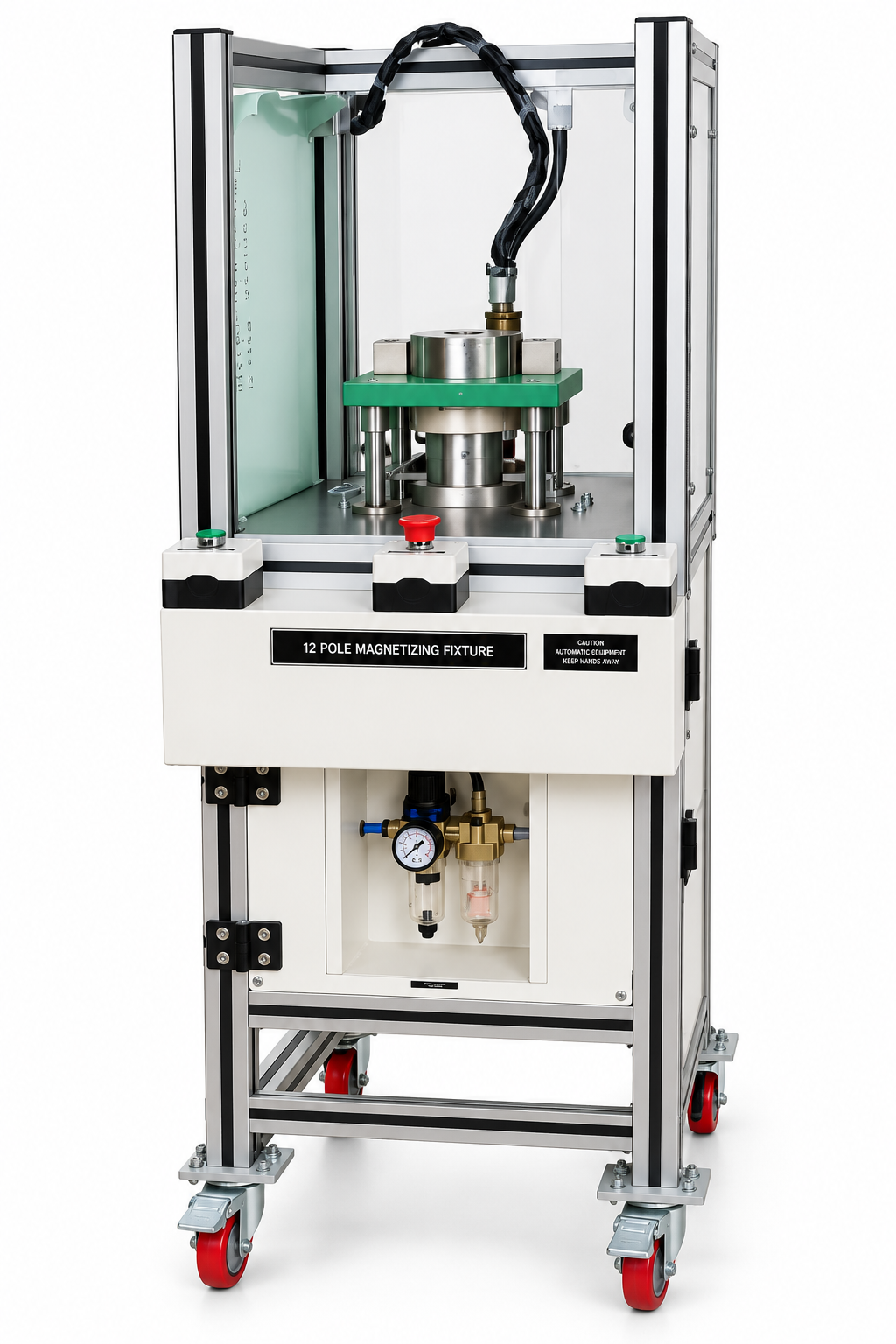
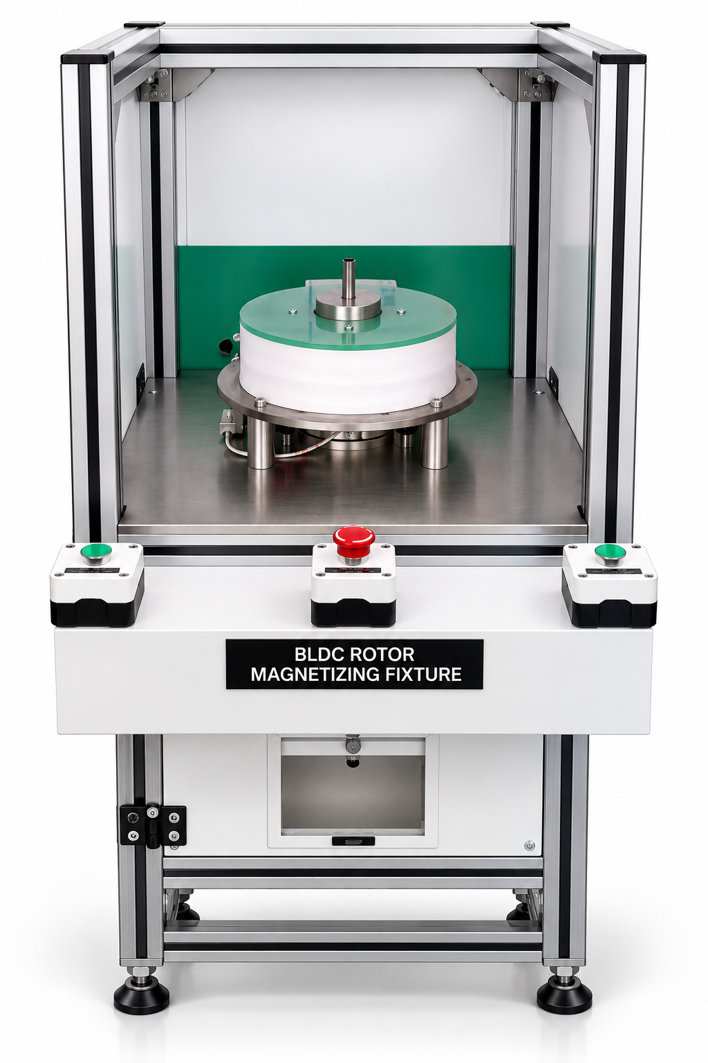
A simple magnet has one north and one south pole. Many of the parts that drive modern products need more: a BLDC rotor commonly carries four, eight or more alternating poles, and an encoder ring for speed sensing can carry many more. Creating those patterns accurately, in one pulse, is the job of a multi-pole magnetizer fixture.
Key takeaways
- A multi-pole magnetizer creates several alternating north and south poles on one part, or on an assembly of magnets, in a single pulse.
- The main specification terms are pole count, pole pitch, skew and whether the part is magnetized from the outside or the inside.
- Fine pole pitches magnetize a shallower layer of the magnet and leave less space for conductors, which limits field and raises heating.
- The fixture must locate the part accurately, so the poles land at the correct angle relative to keys, flats or sensors.
- Pole accuracy is checked with Hall-probe scans, magnetic viewing film and flux measurement.
Where multi-pole magnetizers are used
| Part | Typical pole pattern | Fixture style |
|---|---|---|
| Inner-rotor BLDC and PMSM rotors with surface magnets | Radial poles around the outside | Outer fixture that surrounds the rotor |
| Outer-rotor motors and cup rotors | Radial poles on the inside surface | Inner fixture inserted into the bore |
| DC motor housings with arc magnets | Commonly two or four poles on the inside | Motor housing magnetizer fixture |
| Ring magnets for motors and pumps | Radial poles on the outside or inside diameter | Outer or inner multi-pole fixture |
| Encoder rings and discs | Many fine poles on the circumference or the face | Precision fixture for the track to be read |
Rotor work is the largest single use, especially in the electric motor sector. Encoder and sensor magnets, common in sensors and electronics, demand the tightest pole accuracy.
Key terms
Pole count. The total number of north and south poles. It is always even, and is set by the motor or sensor design.
Pole pitch. The spacing from one pole to the next, quoted as an angle (360° divided by the pole count) or as a distance along the magnetized surface.
Pole transition. The narrow region between adjacent poles where the field changes direction. Sharp, evenly spaced transitions matter most for encoders.
Skew. A deliberate twist of the poles along the length of a rotor, often used to reduce cogging torque. The fixture’s conductors are skewed to match.
Outer vs inner magnetization. An outer fixture surrounds the part and magnetizes its outside surface. An inner fixture fits inside a ring, cup or housing and magnetizes the inside surface.
Radial vs face magnetization. Radial patterns sit on a cylindrical surface; face (axial) patterns sit on the flat face of a disc or ring.
How a multi-pole fixture works
A multi-pole fixture is a steel body, often laminated to limit eddy currents, with conductors laid in slots around the surface that faces the part. Current flows in opposite directions through neighbouring conductors, so the flux between them forms alternating poles. The steel concentrates that flux into the magnet.
During the pulse, the conductors carry kiloamps inside a strong magnetic field and experience large forces. They must be firmly supported and potted so they do not move, rub through their insulation or loosen over thousands of shots. Heat is the other constraint: fine-pitch fixtures use thinner conductors with higher resistance, so they warm up faster and may need cooling or a slower cycle rate.
The multi-pole magnetizer fixture is always designed around one part family, its pole pattern and the magnetizer that drives it.
Pole pitch and magnetization depth
The field from a multi-pole fixture weakens with distance from its surface, and it weakens faster when the poles are close together. A fine pitch therefore magnetizes only a shallow layer of the magnet. That suits a thin encoder track, but on a thick rotor magnet a pitch that is too fine can leave the inner part of the magnet under-magnetized. High-coercivity materials make this harder still; see magnetizer field requirements by material.
Location and angular reference
Every multi-pole fixture needs a way to hold the part at a known angle, using a shaft key, a flat, a dowel or a locating feature on the housing. For Hall-sensor-commutated motors, the angle between the magnetic poles and the sensor positions directly affects how well the motor runs, so this reference is as important as the field itself.
Checking pole accuracy
| Method | What it shows | Typical use |
|---|---|---|
| Hall-probe scan | Field strength around the part, pole positions, pitch error and pole-to-pole symmetry | Process set-up, sampling and detailed quality control |
| Magnetic viewing film | A quick visual image of pole count and boundaries | Fast checks at the machine, catching missing or reversed poles |
| Flux meter with coil | Total flux or magnetic moment | Comparing parts against a reference, checking saturation |
| Peak-current monitoring | Whether each pulse reached the expected current | Every part, in production |
A Hall-probe scan typically rotates the part under a fixed probe and records the field as a waveform. Equal peak heights and evenly spaced zero crossings indicate a good, symmetrical pattern. Uneven peaks can point to part misalignment, fixture wear or variation in the magnets themselves.
Choosing the machine
Multi-pole work usually needs more energy and voltage than a simple shape of the same size, because the field has to be driven through narrow pole regions and steel paths. A dedicated rotor magnetizer pairs the machine with the fixture so pulse length, peak current and cooling suit the part. The multi-pole magnetizer application page outlines typical set-ups.
Need help choosing?
To design a multi-pole fixture, we need the part drawing, magnet material and grade, pole count and pattern, any skew angle, the angular reference and your production rate. A sample part is very helpful.
Request a quotation for a multi-pole magnetizer fixture or contact the SK Enterprises team.